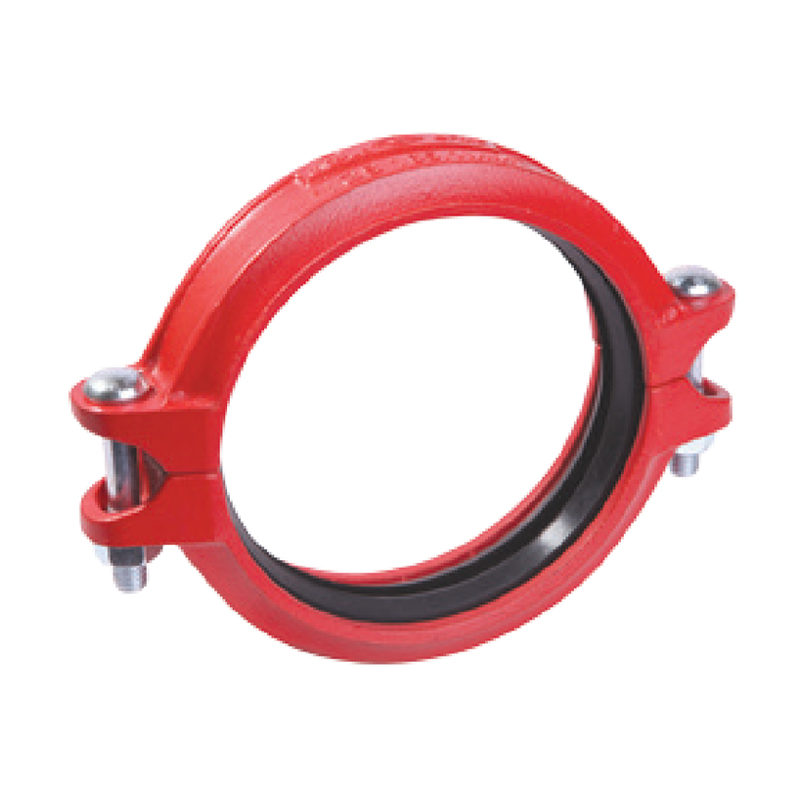
Grooved Coupling
1. Components and Assembly
A grooved coupling mainly consists of three components: the coupling housing, a rubber gasket, and bolts with flange nuts.
- Coupling Housing: It is divided into two – piece halves. These halves are designed to fit snugly into the grooves machined around the entire circumference of the pipes being connected. This mechanical interlock helps prevent axial movement of the pipes relative to each other.
- Rubber Gasket: The rubber gasket has a special “C” – profile design. During assembly, a stretched rubber gasket, which is slightly smaller than the pipe diameter of the two pipe ends, is placed around the pipe ends first, creating an initial seal. Then, the two halves of the coupling housing are positioned around the gasket. The gasket conforms to the shape of the coupling halves. Finally, the coupling halves are bolted together using bolts with oval necks that fit into the matching oval holes of the coupling and flange nuts. Tightening the bolts further improves the sealing performance.
2. Sealing Mechanism
- When the piping system is pressurized, the unique “C” – profile of the rubber gasket comes into play. As the pressure inside the piping system increases, the “pressure reserve” created by the gasket’s profile causes the sealing lips to be pressed more firmly against the gasket seating surface. This forms the third and final seal, making the connection completely leak – proof and airtight. The working temperature range of these gaskets is typically from – 34 °C to + 110 °C.
3. Types and Their Functional Features
- Rigid Grooved Couplings: These couplings provide a very rigid connection, similar to traditional flanged, welded, or threaded piping connections, often with the aid of grip teeth. Once installed, they effectively eliminate or reduce angular deflection, axial displacement, and rotation between the connected pipes. This characteristic makes them suitable for long pipeline installations where precise alignment needs to be maintained.
- Flexible Grooved Couplings: These allow for some degree of angular misalignment and axial movement. This flexibility enables them to be used to create smooth bends in the piping system and absorb thermal expansion and contraction. In certain applications, the use of flexible grooved couplings can even eliminate the need for traditional expansion joints, loops, or other expansion devices.
SKU 个
Category Uncategorized
1. 零件和组装
一个带槽的联轴器主要由三个部件组成:联轴器外壳、橡胶垫片和带法兰螺母的螺栓。
- 耦合器外壳:它被分成两半。这些半部分被设计成能够紧密地卡入连接管道周围加工的凹槽中。这种机械互锁有助于防止管道相对于彼此的轴向移动。
- 橡胶垫片:橡胶垫片具有特殊的“C”形轮廓设计。在组装时,先在管端周围放置一个稍微小于两管端直径的拉伸橡胶垫片,形成初步密封。然后,将耦合器壳体的两半定位在垫片周围。垫片符合耦合器两半的形状。最后,使用与耦合器和法兰螺母的椭圆形孔相匹配的椭圆形脖子螺栓将耦合器两半螺栓连接在一起。进一步拧紧螺栓可以进一步提高密封性能。
2. 密封机制
- 当管道系统加压时,橡胶垫圈的独特的“C”形轮廓发挥作用。随着管道系统内部压力的增加,垫圈轮廓所创造的“压力储备”使密封唇更加紧密地压在垫圈安装面上。这形成了第三个也是最后一个密封,使连接完全无泄漏且气密。这些垫圈的正常工作温度范围通常为-34°C至+110°C。
3. 类型及其功能特征
- 刚性槽形联轴器:这些联轴器提供非常刚性的连接,类似于传统的法兰、焊接或螺纹管道连接,通常借助夹紧齿。一旦安装,它们有效地消除或减少了连接管道之间的角偏移、轴向位移和旋转。这一特性使它们适用于需要保持精确对齐的长管道安装。
- 柔性槽形联轴器:这些允许一定的角度偏移和轴向移动。这种灵活性使它们能够用于在管道系统中创建平滑的弯曲,并吸收热膨胀和收缩。在某些应用中,使用柔性槽形联轴器甚至可以消除对传统膨胀节、循环或其他膨胀装置的需求。
Details
Be the first to review “Grooved Coupling” Cancel reply


Reviews
There are no reviews yet.